

How To Repair Garage Door Opener Motor Worm Gear
How to Replace the Drive Gear in your Garage Door Opener
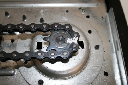
Its 6am and yous are leaving for work. You press the garage door opener wall button and hear a subtle hum from your electric motor but the door failed to motility. If your garage doors springs are in tact chances are yous garage door openers main drive gear has failed. You can hands inspect your bulldoze gears by unplugging your garage door opener and removing the metal cover. The main bulldoze gear is made of a white plastic that typically is the weak link in the opener. Many things can cause this gear to fail. Some causes of wear are:
- Garage door out of balance (Springs broke or in need of aligning)
- Chain to tight a
- Old age
- Excessive use or high cycle
- Factory defect or lack of grease at time of industry
Replacing the large white gear is a low toll, quick and piece of cake practice information technology yourself repair as long every bit you have a few unproblematic hand tools and follow the safety precautions. These gears can be purchased online in a diverseness of levels of components. The following gears and gear kits work with most all models of LiftMaster, Sears Craftsman and Chamberlain brand garage door openers. When ordering the full gear kits that include the sprockets, please make sure that y'all know if your garage door opener is a chain or belt drive equally there are differnet part numbers. If yous just want just the gear (such as the 41A2817-CR) then the main bulldoze gear will be the same.
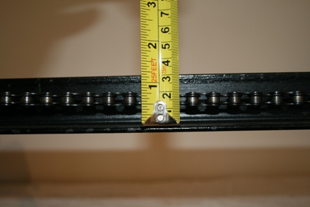
41A2817-CR Gear and grease only. Works with all chain and belt models from 1984 to nowadays LiftMaster, Sears Craftsman and Chamberlain openers using a big white gear that is ii three/4" x one/ii" broad, with a one/2" bore.
41C4220A this kit includes all of the components above in the and includes the drive shaft and sprocket also. I recommend this kit if you do not take the 5/32� punch equally mentioned in our tools requires section. Information technology is cheaper to purchase this kit than it would be to run out and buy the punch needed to remove the curl pins to supervene upon the gear only. The primary drive gears comes already installed on the shaft (very convenient) This repair kit is FOR Chain Bulldoze MODELS Only. If you have a belt bulldoze model run into part number 41A4885-two or 41A4885-five below.
41A4885-ii utilize this kit if you wish to replace the consummate drive shaft and chugalug pulley assembly on belt drive garage door openers used between 1984 and 2001. For newer models from 2002 to present see part number 41A4885-v below
41A4885-5 use this kit if y'all wish to supersede the complete drive shaft and belt caster associates on belt drive garage door openers used between 2002 to present.
In the endeavour to educate homeowners on the procedure nosotros have produced this commodity to guide yous through the process footstep by pace. Later reading this article you cam make an educated determination on whether or not to endeavour this procedure yourself.
Before you get started it is of import for you to have a list of the few simple tools needed to accomplish this project:
- Hammer
- �� wrench or adjustable wrench or pliers
- three/8� Socket or Nut Commuter
- ane/4� Socket or Nut Driver
- five/16� Socket or Nut Driver
- Flat Standard Screwdriver
- 5/32� Punch or like
~WA RNING ~
To prevent possible SERIOUS INJURY or even Decease from electrocution,
Ever Disconnect the power cord from your garage door from the
outlet before proceeding with any inspection or repair.
Pace #1
Make certain your garage door opener is unplugged. This footstep insures that no ane unintentionally attempts to open or close the garage door while you are working on it or yous do not accidentally activate the door while servicing it.
Step #2
Disconnect the door from the outer trolley past manually pulling the cerise disconnect rope and manually close the garage door.
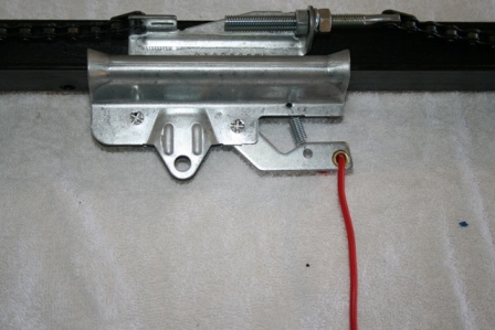
~CAUTION~
The Garage door MUST exist in the fully closed position
during all repairs and inspection.
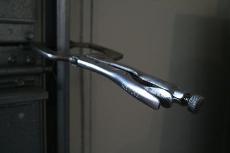
Assuring that your garage door is closed will reassure that your door will not fall or brand any movement that would cause injury or startle you. We recommend that once the door is airtight that you clamp the door down using a vise grip or clamp to a higher place one of the rollers to forestall the door from being opened from the exterior. See photo instance below.
Step #3
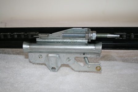
Slacken the chain or belts tension by loosing the tension nut on the garage door opener trolley. Typically this is nut and tin can be adapted with a �� wrench
Footstep #4
Remove the sprocket or chugalug pulley retainer cap. Normally this has a clip on the back if you press in information technology will release.
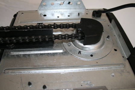
Step #5
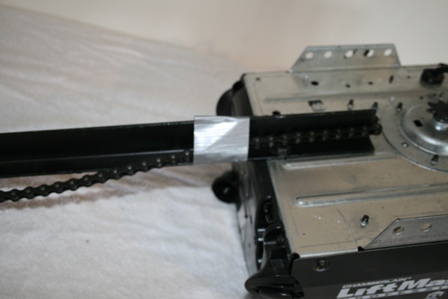
I ever recommend marking the position of the chain or chugalug to the sprocket prior to removing. This tin can easily exist washed with white out, tape or any other means. This step helps clinch that your chain or belt gets reinstalled in the correct position and makes for quick and piece of cake reference if needed afterwards. Remove the chain or belt from the sprocket and then slide the inner trolley to the closed position until it engages the outer trolley. Place loose concatenation/chugalug on the end of the rail closest to the sprocket. I typically duct tape the concatenation to prevent it from falling to the flooring and getting all twisted and dirty.
Pace #six
It is now time to remove both end covers and the primary housing. The cease cover are each attached by three or four �� head screws that can be removed with a �� nut driver or socket. Be sure to unplug the wire to the circuit lath.
Step #7
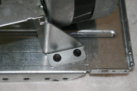
Remove the retaining clip and the bulldoze gear for the limits. Also at this time remove the limit switch assembly by squeezing the sides just below the bracket by the drive gears. At that place is no demand to disconnect the wires as it is ok to leave this limit assembly hang by the wires. Do not make any adjustments to the limit assembly screws, this will insure that there is minimal adjustment needed to the limits after you complete your repair and run your garage door opener.
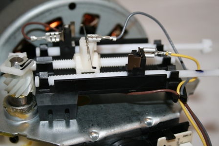
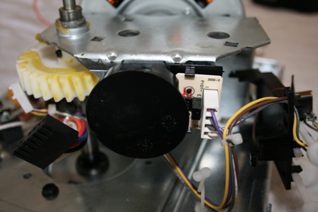
Step #eight
Now its fourth dimension to remove the RPM sensor this tin be easily done by unplugging the wire harness and remove the RPM sensor from the securing tabs.
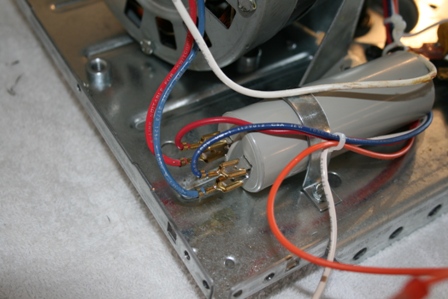
Step #9
Disconnect the cherry-red, blue and white wires from the motor. Information technology is of import that y'all annotation where these wires go. The same color wires go to the same terminals on the capacitor carmine/red and blue/blue. See photograph examples below. These photos are a good reference if you happen to forget.
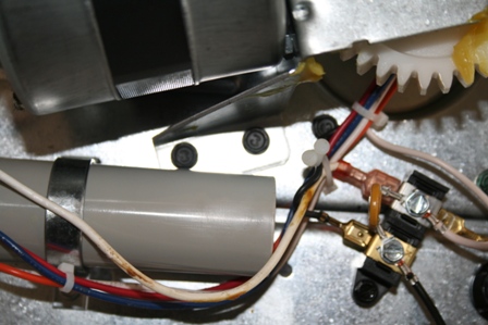
Pace #10
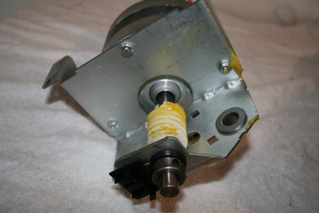
Remove the 4 5/16� hex head screw�south that hold the motor assembly to the frame of the garage door opener. Be sure to put your paw under the motor earlier removing the terminal spiral to preclude the motor from falling. Slide the motor assembly off the drive shaft and place in a safe place. (Not on top of the ladder for obvious reasons) Run across photo�due south below.
Step #11
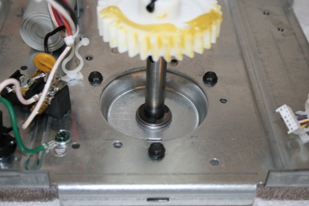
Remove the 3 hex head screws belongings the sprocket assembly to the main chassis using a 5/sixteen� nut driver or socket. Now it is time to decide if you lot want to supervene upon the principal gear only all units 1984 to present chain and belt drive use part number 41A2817-CR or the main gear and worm gear function number 41A2817 or the unabridged sprocket 41C4220A for all concatenation drive models 1984 to nowadays. For belt drive models if you wish to alter the caster shaft use part number 41A4885-ii from 1984 to nowadays and if your belt drive unit was made from 2002 to present use role number 41A4885-5 all these parts are very affordable and tin be purchased online at www.stardoorparts.com . Run into photo below to locate these screws.
Pace #12
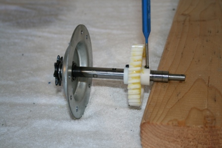
Skip this footstep if you are replacing the entire gear and sprocket or pulley assembly 41C4220A, 41A4885-2, 41A4885-5. If you are going to replace the drive gear support the driveshaft on a block of wood and drive the lower ringlet pin/Tension pin out with a v/32� punch. See photograph case below.
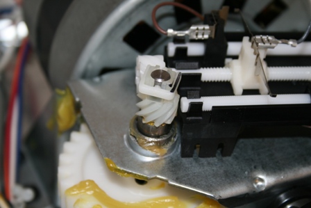
Footstep #xiii
Remove and supervene upon the worm gear. In most cases it is non necessary to replace the worm gear unless it shows signs of wear. If you wish to supersede this gear remove the shaft collar with a 1/8� hex wrench. Please be sure to note the location of each of these components as you disassemble and then yous can re-install in proper guild. When you receive you kit part number 41A2817 or 41C4220A you volition detect there are parts non used in your model this is because these kits are universal and work with many models of Sears, Craftsman, Wayne Dalton, Master Mechanic, Liftmaster, Truthful Value and other brands of garage doors openers. Only replace the parts that are used on your garage door opener. Remove the three nuts that agree the motor to the frame and so remove the worm gear. Install the new worm gear making sure the gyre pin is properly seated in the new gear. Re-install other components in reverse club. Subsequently you lot consummate this assembly I recommend you lube the worm gear and so y'all do not forget.
Step #xiv
Begin reassembly in reverse lodge. Exist sure to thoroughly lube the main bulldoze gear and that grease is on each and every tooth. Attach the gear and sprocket or caster assembly to the main chassis with the three 5/16� head screws. Install the assembled motor frame to the chassis with the four 5/16� head screws and reattach the red, blueish and white wires; at present install the limit assembly and the limit drive gear making sure they mesh properly. Y'all tin at present install the RPM sensor and reconnect wires. Install the metal encompass and end panels, be sure to plug in the circuit board and reconnect photo eye and push wires.
Step #15
Reconnect the ability cord to the opener and bike the opener until the sprocket completes a complete clockwise cycle. The trolley must be in the fully down position before installing the concatenation. Now you can remove the tape from the runway and reinstall the chain. The concatenation and sprocket reference marker should be shut to lining up. Tighten the concatenation so that the chain is �� to a higher place the base of the rail at midpoint for �T� style rails and �� for square tube rails. Secure the chain tightening lock nut.
WARNING
Annotation when adjusting and testing your garage door motor it is important
to make sure no ane is in the path of the moving door.
CAUTION
It is important to know when testing your garage door opener it is possible to over bicycle the motor
and accept the motor temporarily overheat and stop operating.
To prevent this try and non operate the door opener more than 10 cycles
without giving information technology five-10 minutes to cool off
Step #16
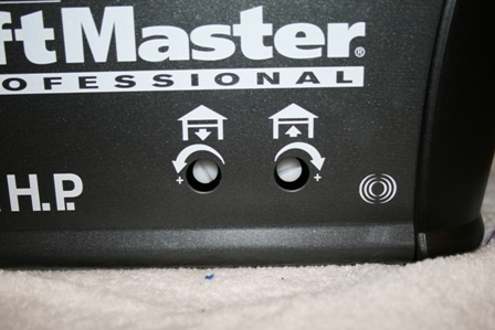
At present run the opener and exam to see if the door opens to the correct position and closes to the correct position. If you need to make adjustments utilize the travel adjustments screws to make fine adjustments. I recommend only making slight adjustments � turn or less at a time. For reference 1 full turn of the spiral equals approx 2� of travel on � and � HP models and 3� on � HP models.
Step #17
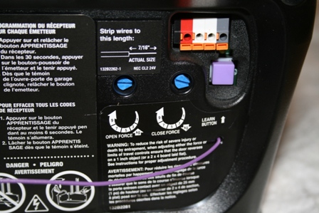
Once you have your doors travel adjustment correct it is time to adapt the strength. This is the pressure that information technology takes to assure your door opener volition operate safely. The first pace in this process is to check the down force. With the door open simply actuate the garage door opener and when the door reaches the half way betoken grasp the door from the bottom and attempt and terminate information technology. If the door is hard to terminate or does not stop decrease the down force adjustment in pocket-size increments until it reverse upon reasonable strength. If the door does not close and the lite begins to glimmer increase the down force adjustment in small increments until you can check the reversal at half fashion. Adjusting the force does not guarantee that your operator will opposite on 1-one/2� object at the floor. For more information on adjusting the reversal at the flooring run into your owner�s manual or telephone call the manufacture.
Some of the models this article covers are listed beneath and many models are left out. Please eastward-mail service us if your model was non shown merely this commodity helped you out contact united states of america and let united states of america know so we tin can add together your brand and model number to the listing to help out more people.
Chamberlain 1100, 1200, 2100, 2200, 4100, 4200, 4893OD, 5100, 6200, 710WHC, 711WHC, 7200, 7220, 7320, 7420, 7520D, 8100, 8100M, 8200, 9200, CG40, CG40D, CG42D, CSO, HD200D, HD600, PD100, PD200, PD210, PD210D, PD212, PD212D, PD600, PD610, PD610D, PD612K, PD612KLD, PD752, PD752D, PD758D, PD758S, WD822K, WD822KD, WD822KS, WD912K, WD912KS, WD922K Raynor 2245RGD, 2595RGD, 2585RGD, 2280RGD, 2265RGD, Pilot, Aviator, Edeavor, Navigator. Fits these Liftmaster Models: 985, 1240, 1240R, 1245, 1245R, 1245LK, 1246, 1246R, 1250, 1255, 1255R, 1256, 1256R, 1260, 1260LK, 1265, 1270, 1280, 1280R, 1345, 1346, 1356, 215WD, 220WD, 2245, 2255, 2265, 2565, 2280, 2575, 2580, 2585, 2595, 315WD, 320WD, 3245, 3255, 3265, 3280, 3575, 3585, 3595, ATS211, ATS211R, ATS211X, ATS2113X All Sears Craftsman chain and belt drive models 139.53990, 139.53992, 139.53914, 139.53985, 139.53930, 139.53635, 139.53964, 139.53660, 139.53920, 139.53939, 139.184050, 139.18803, 139.18805, 139.18814, 139.18830, 139.18850, 139.18851 and all chain and chugalug operators from 1984 to nowadays.


How To Repair Garage Door Opener Motor Worm Gear,
Source: https://www.stardoorparts.com/How-to-replace-your-garage-door-opener-gears-s/30.htm
Posted by: pollitthicand.blogspot.com
0 Response to "How To Repair Garage Door Opener Motor Worm Gear"
Post a Comment